RC TRITEC Swiss quality tritium labeling for luxury and medicine
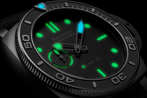
Swiss Super-LumiNova
®
Mit maximaler Nachleuchtkraft zur ersten Wahl der Schweizer Uhrenindustrie.
Swiss Super-LumiNova
®
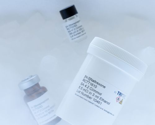
Isotopen & Technologie
Mehr als 80 Jahre Erfahrung in der sicheren Anwendung von Radioaktivität.
Isotopen & Technologie